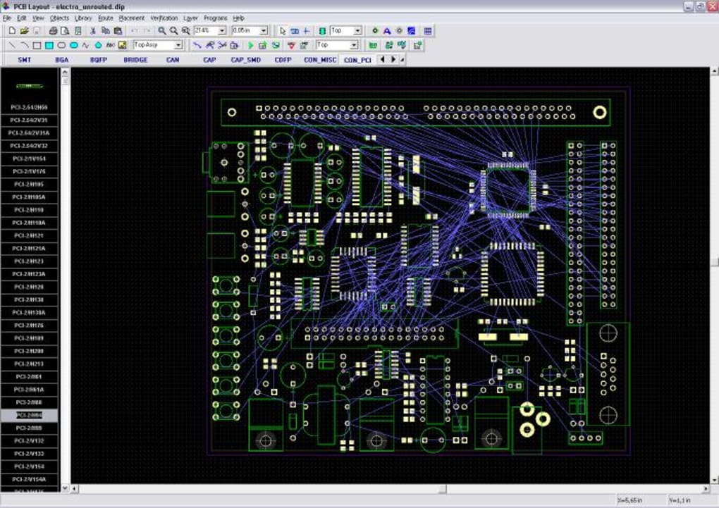

I may alter the original pours to use part of the inner layers to accommodate most of the segment ‘buses’ for the 7-segment displays. My next step is to work with the previous successful 2-layer route and edit that to manually move the Vdd / Vcc / ground traces to the two inner layers. Obviously a different approach is needed. I wound up with these planes mercilessly slashed into several unconnected sections and multiple ratlines remaining. I had expected it to merely route all the Vdd, Vcc, and ground connections to the two inner layers and keep all the signal traces to the front / back copper. I then added the two inner layers, defined the boundaries for the needed pours, then sent it back into DipTrace’s autorouter. Download DipTrace 4.1.3 Full + 3D Libraries Size: 1.8 GB Google drive (32bit): DOWNLOAD Google drive (64bit): DOWNLOAD 3D Libraries: DOWNLOAD Pass: sbz Installation and activation Instructions in readme. This process worked well with the initial design and corrected version.

So I have a PC board design that I’m reworking from 2 layers to 4 on the advice of a friend, as it has 21 ICs, ten 7-segment displays, and 6 LEDs.Īs KiCAD currently does not have an autorouter, I’ve been using DipTrace for that functionality (importing directly then using Eagle format to bring the design back into KiCAD for final silkscreen adjustments, Gerber generation etc.)


 0 kommentar(er)
